OpenRGB Setup1:
IMPORTANT FOR LINUX USERS
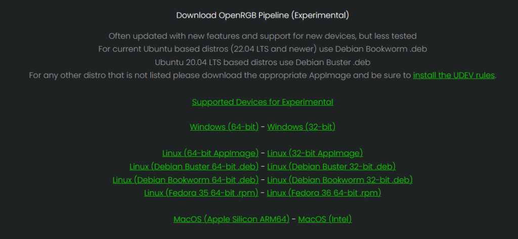
It seems that OpenRGB v0.9 which is the latest stable release of OpenRGB has issues communicating with the RGB LED module when installed on Linux. People on the forum have reported that using the experimental release of OpenRGB fixes these issues. Scroll to the bottom of https://openrgb.org/ to download.
Thank you for purchasing an RGB LED Matrix module! Your module came programmed with Adalight compatible firmware. This makes it possible to use OpenRGB to control the modules. I have created an instructional video tutorial to set up OpenRGB.
The double led script is to reorder the LED indicies when you have two LED matrix modules side by side in the VMap editor.
Re-programming the Module:
Your module comes programmed with the correct firmware already.
But, If you would like to re-program the module with the Adalight firmware it originally shipped with to use the RGB LED module with OpenRGB. Then, please follow these steps.
- Remove the LED module from your laptop.
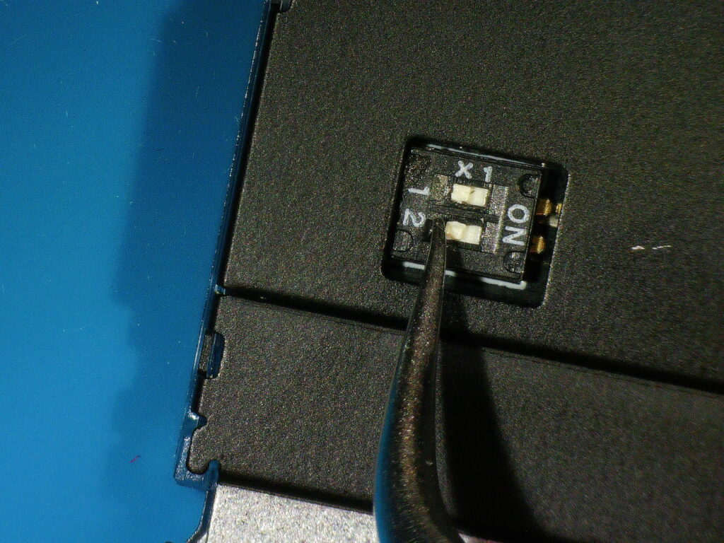
- Flip over the module and locate the two switches on the back near the main board connector.
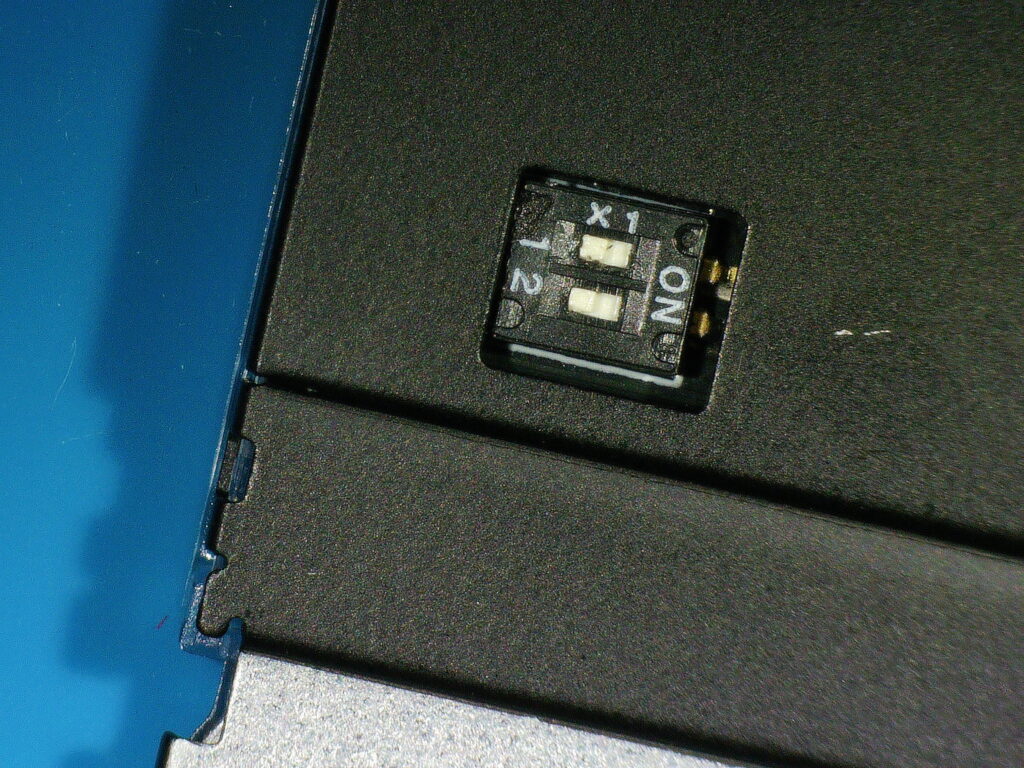
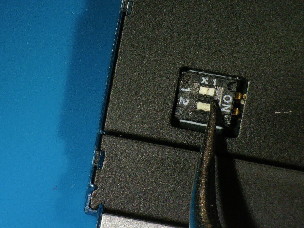
- Using tweezers or a small screwdriver. GENTLY push the switch labeled “2” from the left to the right. The raised bump on the switch should be next to the label “ON”.
- Install the LED module into your Framework Laptop 16 input deck.
- Verify that the RP2 boot device appears in your operating system. Use Device Manager if you are on Windows. A folder should also appear in your file manager for the internal storage on the RP2040 microcontroller.
- Download the Arduino IDE. I recommend using the latest version 2.X.X edition. Once you have the IDE installed, follow the steps in this Adafruit guide to install the RP2040 core into the Arduino IDE. Stop where it says “Choose Your Board”.
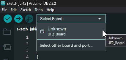
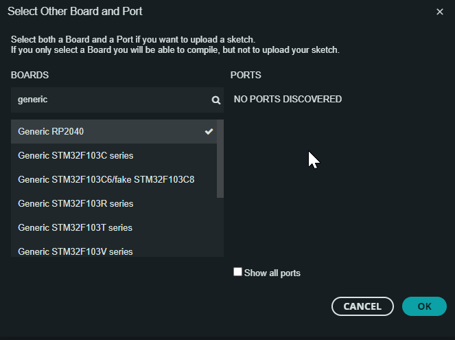
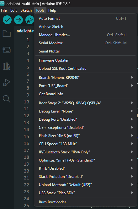
- In the Board Manager in the Arduino IDE select the “UF2_board” option. Then search for “Generic RP2040” and click it. It’s ok if the IDE says “NO PORTS DISCOVERED” on the right. Make sure “Generic RP2040” has a check mark next to it and click “OK”. IMPORTANT, under the “Tools” menu in the Arduino IDE you’ll need to make sure you pick these settings:
- Boot Stage 2: “W25Q16JVxQ QSPI /4”
- Flash Size: “4MB (no FS)”
- USB Stack: “Pico SDK”
- Everything else can be left default.
- Now download the Arduino code from my GitHub here: https://github.com/corndog2000/adalight-multi-strip
- Open the adalight-multi-strip.ino file in the Arduino IDE. If you get a warning saying that the file must be in a folder, just click OK and the IDE will move the .ino file into the correct folder.
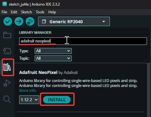
- You need to install the Adafruit NeoPixel library inside of the Arduino IDE for the code to compile. On the left side of the IDE select the icon that looks like a stack of books. Type in “Adafruit NeoPixel” and click install on the Adafruit NeoPixel library that should appear at the top.
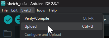
- After that library installs, then you can click on the “Sketch” menu item. Then, click on “Upload”. The sketch should compile and then upload to the LED matrix.
- Once the IDE says “Done uploading” you need to remove the LED matrix from the laptop.
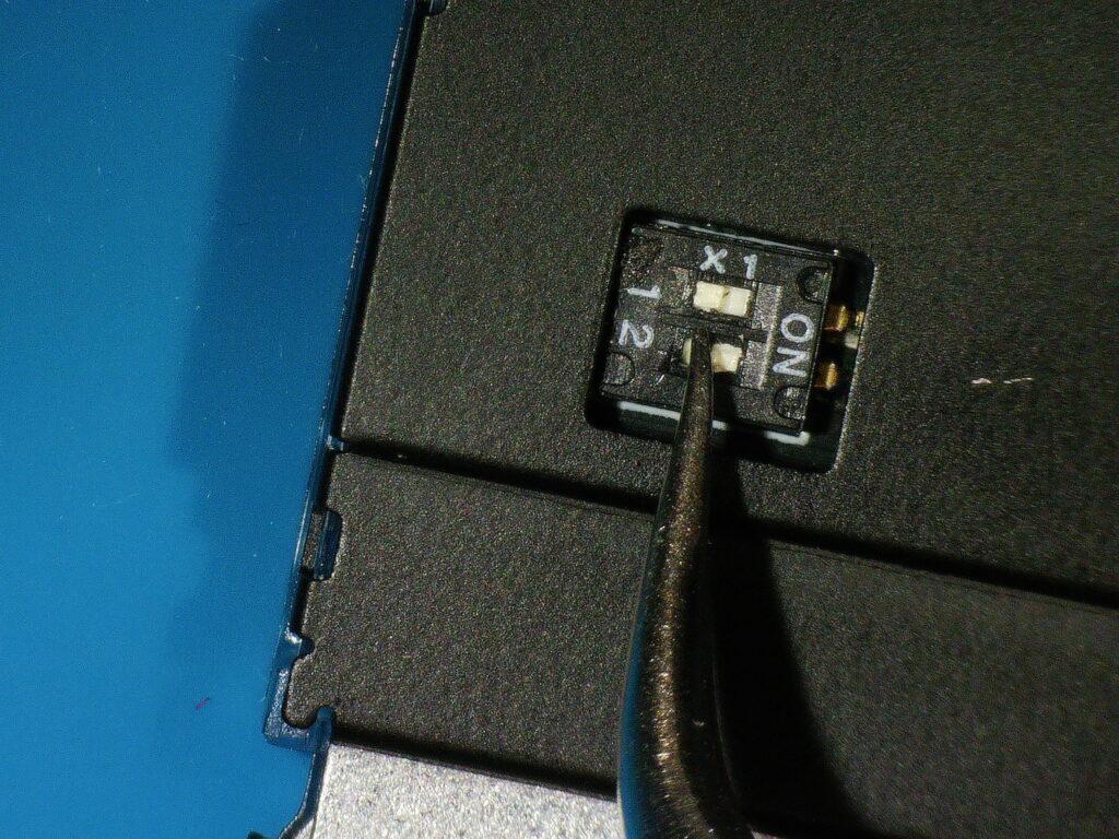
- Flip over the module to access the switches again.
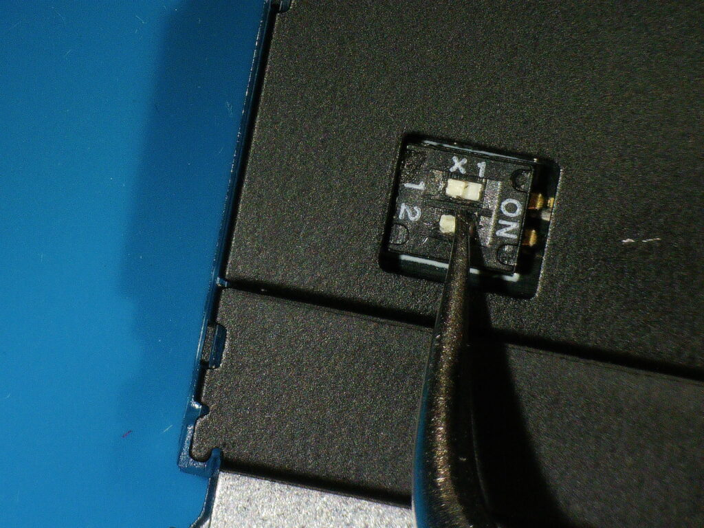
- GENTLY Slide the switch labeled “2” away from the label “ON”. This will make sure the RP2040 will not erase its code when powered on.
- Finally, install the module back into your laptop. You can now follow the OpenRGB instructions to set up your RGB LED matrix.
Installing CircuitPython on the RP2040:
I’ll be adding documentation soon with easier to understand pinouts and instructions for flashing CircuitPython. But, the instructions for flashing CircuitPython are the same as any RP2040 microcontroller. Except, you’ll still need to use switch “2” on the back of the module to get into the UF2 bootloader.
- Updated: 20:00 Eastern US – July 8th, 2024 ↩︎